Hi all!
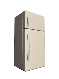
In this tutorial you will learn how to create a simple refrigerator using mainly Chamfer boxes.
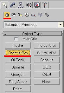
1. Create a Chamfer box on a top view....
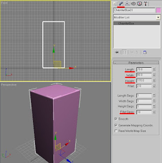
..and in a Modify panel change its parameters to 70, 80, 170; Fillet-2 and Fillet Segments-10 or just measure your own fridge and work from that.
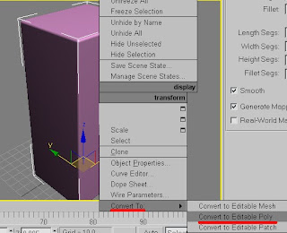
2. Right click the box and convert it to Editable poly.
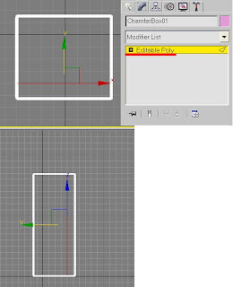
3. Go to a Modify panel and choose Edge sub-object. Connect Top edges as shown on the image and move them right a bit.
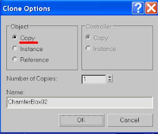
4. Release Modify and Copy (Shift + Drag) the box.
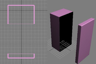
5. In both boxes delete vertexes so you have a main body part and a door part.
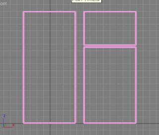
6. Choose the door part and duplicate it. By moving vertexes up create a Freezer door and by down – main body door.
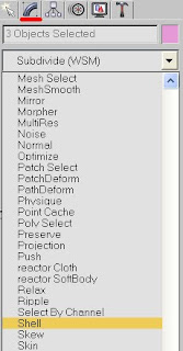
7. If you hit Render (F9) u will probably notice that some, or even most of the parts are missing. This is why we deleted some of the vertexes before. To fix that choose all parts (Ctrl+A) and choose Shell modifier in a Modify panel.
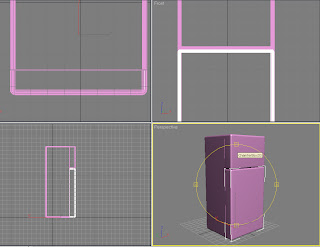
8. Arrange all the parts so it looks like fridge and hit Render (F9).
Now we'll add some details.
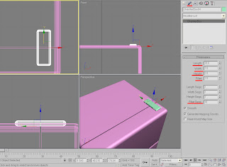
9. There is a part on the top of the fridge that connects the freezer door to the main body. To make one create another Chamfer box on a top view measured 18, 5, 2; Fillet 1 and Fillet Segments 10and place it on the top of the fridge.
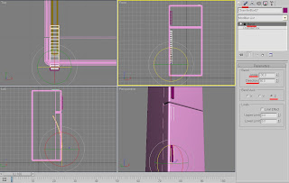
10. Also, as you've probably noticed before, every fridge usually has some kind of legs that that it stands on, so you can either put some Boxes under it or Extrude them from the main body.
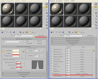
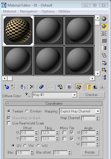
Time to create some Materials – so press M on your keyboard.
11. For the Fridge I used an Off-white color with a Standard material, Specular Level of 96 and Glossiness – 54. Scroll down to Maps and set Refraction to 15 and a Raytrace material (leave as is).
12. The handle is some kind of a glossy metallic surface, so I used Standard material and a Multy-layer shader.
13. For first specular level set Color to 229, 229, 229 (light grey), Level to 537, Glossiness 19, Anisotropy 78.
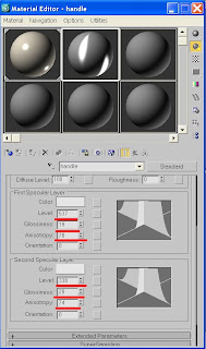
14. For second specular level set Color to 229, 229, 229 (light grey), Level to 338, Glossiness 28, Anisotropy 74.
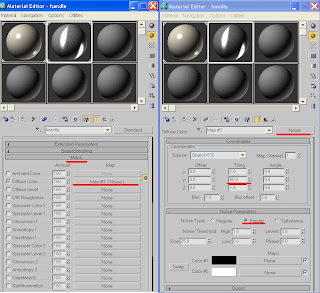
16. Scroll down to Maps and set a Diffuse color to Noise. Change Tiling Y to 50; Fractal.
17. Set Color 1 to Raytrace and leave the rest as is.
Apply materials to your refrigerator.
18. Hit 8 to change your background color to White and then hit render (F9).
The fridge is ready.
If you have any questions regarding this tutorial - don’t hesitate to ask me.
"Weekly doodles" is a drawing blog. It's about learning how to draw, sketch and develop these skills. It is also a self-report and a procrastination getaway, a commitment to me and everyone around on becoming a skilled illustrator. If you wish to learn how to draw and develop your creative and technical side, then please join me on this amazing journey. You will find here not only drawing lessons but also Illustrator tutorials, utilization DIYs and many more. Enjoy!
August 28, 2009
June 29, 2009
Making of Glasses with 3ds Max
Summer is here, so it's time to model some glasses!!! These are actually regular ones but with some material adaptation you can use the same tutorial to create some sunglasses too.
So...
1. On a top view create a box measured 8-140-50 with 2 Width segments.
2. Right click the object to convert it to Editable Poly. Go to a modifier panel and choose Vertex sub-object and delete a left part of the box.
3. Now if you look at the Perspective view you’ll notice that deleted Vertexes created a hole in our box. To fix it we should choose an open Border and Cap it.
4. Mirror – Instance this box and Move it aside. This way, while working on one part only, we’ll be seeing a progress on both parts. We will connect them later.
5. Connect opposite splines 3 times and other opposites twice.
6. Choose the shown polygon and extrude it outside. It will be the bridge holder (the nose part).
7. Start moving the vertexes on a Front view to give it a basic glasses frame shape. Use reference image or your own sunglasses for that matter. When finished, go to a Modifier panel - Subdivision Surface and check Use NURBs with Iterations 2 and uncheck afterwards.
8. Choose central Polygons and Bevel them inside twice – first for the (0;-4) and second for the lens (-3;3). Do the same with the back side of the glasses. Check and uncheck NURMS sbdv for a quick check. If you wish to make some changes – to make a lens thicker or thinner, or to change the shape of your glasses – just keep moving the Vertexes. Just do it now, while we’re at the beginning.
9. To create nose part choose one half and convert it to Editable poly again.
10. Before creating an Earpiece take another look at it. You’ll notice that it is not totally straight, but a bit curved. Choose an upper side polygon and Extrude it a bit - twice. If it goes up or down – fix it by moving Vertexes.
Now from the back of the second part – One long extrude and two small ones. Move and Rotate it Vertexes to give it a curved shape Connect central Edges, if needed. Check and uncheck NURMS subdvs again.
11. Time to connect the two parts together.
12. Choose both parts and convert them to Editable Poly again (right-click). Choose one part and Attach it another part. Now the two glasses halves are chosen.
13. Remember the nose bridge? Choose both polygons as shown (Choose – Ctrl - choose) and press Bridge.
Now we have one solid pair of glasses. Make adjustments if needed – by connecting Edges and moving Vertexes.
14. Since glasses are usually concaved, move and rotate your vertexes so it fits the shape of the head.
15. Now we'll start adding materials. Since its one single object we'll obviously use a multi/sub-object color.
16. Press M for material editor. Change Standard to Multi/Sub-object and Set the material number to 2. Name them Frame and Lens. For a frame I used Black for Ambient color with a Specular level of 107 and Glossiness of 26 – ID 1.
17. For a lens I used White for Ambient, 96 for Specular level and 32 for Glossiness – ID 2.
18. Choose your object and Assign materials it and make them Visible in Viewports.
19. While glasses are still chosen, press Element in a modifier panel and choose glasses again. You will see that all polygons have been chosen.
20. Scroll down to Polygon Properties and set ID color to 1. That will color our glasses to black.
21. Choose lens polygons – front and back – and set their ID to 2.
22. If you haven’t done it yet, check NURMS Subdvs to make the glasses smooth.
23. Hit 8 to change the background to white and F9 to render.
24. That’s it. The glasses are ready.
25. If you have any questions regarding this tutorial - don’t hesitate to ask me.
June 15, 2009
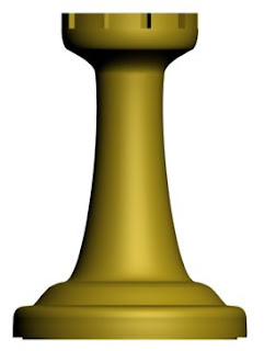
How to create a chess Rook with 3ds max tutorial
In this tutorial you will learn how to create a Chess Rook. This will be one of a Chess Set tutorials explaining how to create a Pawn , a rook, a knight and a chessboard itself.
As usual, you will need a reference image before you start creating anything. You can upload it here or find/create another one.
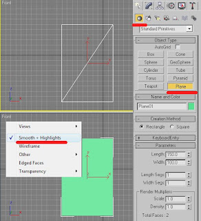
1. On a front view create a 150 x 100 plane. Then right-click the Front View and check Smooth and Highlight. This will allow you to create your pawn easily.
2. Press M and choose an empty slot. Go to Diffuse color, hit the grey square near it and choose a Bitmap to import the reference image. Apply the image to the Plane.
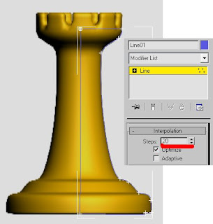
3. Of a front view outline only a half of the reference pawn using a Line tool. Close spline when you finish outlining. If the outline is not as accurate as it supposed to choose Vertexes in a Modifier menu and right click your mouse. Click Bezier Corners. Now you can adjust each corner handle separately. When finished outlining go to interpolation and change to 20 steps to make the line smoother. If you need to add some vertexes, press Refine and hit the line when little white cross appears above it.
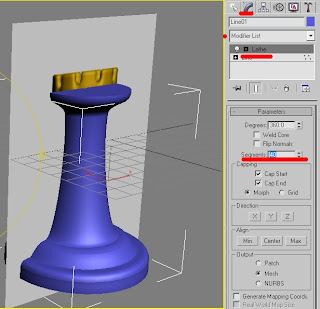
4. When you are pleased with the outline, go to the Modifier menu and choose a Lathe modifier. You will see that your outline became 3dimensional. In Parameters press Min button to set the pawn right. Change Segments to 40. Keep smoothing the corners, if needed.
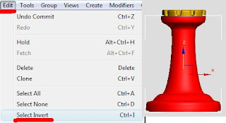
5. Now choose the object, right click it and convert to editable poly. Press F4 to see the wireframe, choose all polygons except the upper one's. Go to Edit + Select + Invert, to choose only upper polygons.
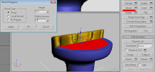
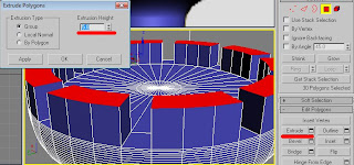
6. Go to Bevel and set its High to zero and outline to -4. Now choose polygons as shown on the image and extrude them – High 5.
7. Delete the reference plane.
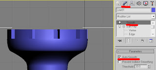
8. Choose Smooth in modifiers and check AutoSmooth.
9. Apply an ochre color to it (177, 148, 26) and hit F9 to render.
That’s it. The rock is ready
If you have any questions regarding this tutorial, do not hesitate to ask me.
June 10, 2009
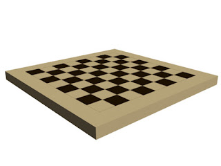
How to create a Chess Board with 3dmax tutorial
This time i will show you how to model a Chess Board.
The two things you must remember when creating a chess board is that it is square and that it divided to 8x8 colorful inside squares.
So …
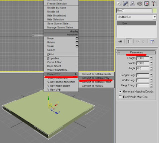
1. The first thing you want to do is to create a 100x100x6 box. Right-click any view and choose Editable poly. Go to Modifier list and choose Edge sub-object.
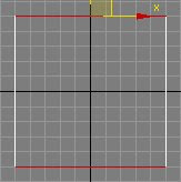
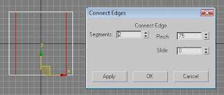
2. While standing on a Top view choose two opposite sides and Connect them (press the little square.
See image for parameters. Repeat this step with other opposite sides.
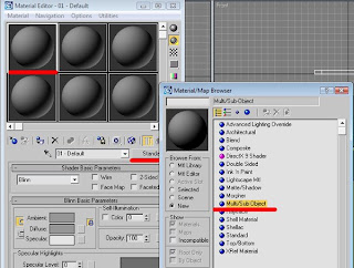
3. Press M and choose an empty slot. In a Material/Map browser choose a Multi/Sub-objects. This will allow us to use several colors on the same object. Choose Discard Old materials.
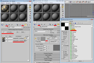
4. Since we will use only 2 colors, set the color number on 2. The first color will be a basic bright brown. I chose 254, 228, 171 for that matter.
5. The other will represent a chess board itself with two colors – bright and dark one. Click the Material # button. Now click the Diffuse color button to choose a Checker material. Use 254, 228, 171 for bright and 40, 23, 0 for dark. Make it visible. Notice that each color has its ID number. Remember that so we could work with it later.
6. Apply the materials to our board.
Whatever happened with your colors it might not look the way it should be. But we'll fix it in aminute.
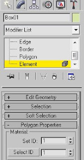
7. Choose the box, go to the Modifier list and choose Element sub-object. After it chooses the entire box go to polygon properties. Remember the Material ID's? It was 1 for bright and 2 for Checkers. Set the ID's to 1.
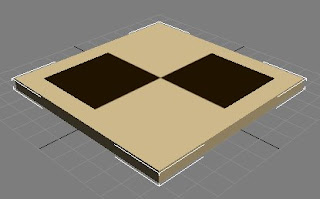
8. Now choose the upper polygon only and set ID's to 2. Now you see your materials how they should be. Almost.
9. Go back to the Checker material and set the Tiling number to 12. You will see the changes immediately.
10. Change the background to white (8) and hit F9 to render.
That’s it.
If you have any question regarding this tutorial, don’t hesitate to ask me.
Subscribe to:
Posts (Atom)